Snowfall - A very special video game controller
Here is a short Youtube video explaining what this post it about. How did I do it? I will try to go through the main steps in the following.
Understanding the wiring and connecting the Arduino
To use the mat as a game controller, I had to first understand its internal wiring before setting up a connection to the Arduino microcontroller. So I freed the PCB along with its wiring of the red plastic hull that was originally containing it. After becoming almost insane trying to figure out the totally weird wiring inside the mat by manually checking the connections from outside with a multimeter, I finally decided to just cut the mat open, which made everything much easier and saved my sanity ;)
Part 1 - LEDs
Intuitively (and naively), for ten LEDs you would expect two connections for each LED and therefore 20 connections in total. But it seems that especially when dealing with cheap toy electronics, it is never that easy. Every cable drives up costs and so they favour more complicated wiring when it is less costly to produce. In this mat, there are 7 cables, each with a different colour (at least they did me that favour!). The setup can be seen in this picture:
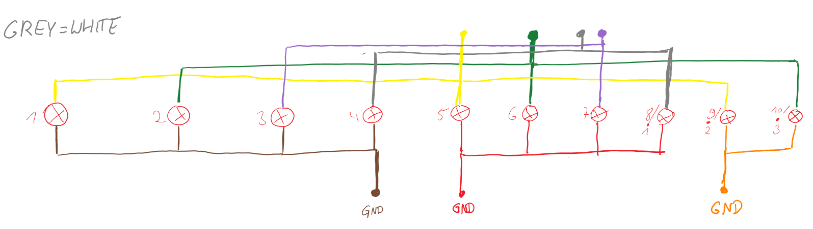
So if you want to light up the LED number 2 for example, you have to apply a current to the green cable, and pull the brown cable to the ground to allow the current to flow. In general, for every LED there is a specific combination of two buttons that you have to set. But as if that is not complicated enough, you introduce some dependencies with this setup. What if you wanted to light up LED 1 and 6 simultaneously? You would have to supply the yellow cable with current for LED 1 and the green one for LED 6. Also, the brown and red cables would both have to act as ground. But wait a minute - in this configuration, the LEDs 2 and 5 would light up too, as both are now exposed to the same current as LEDs 1 and 6. I worked around this dependency with a “cheap” trick: When multiple LEDs should be activated, I light up one LED after the other, but switch between the LEDs at such a high frequency (about 5 ms for every LED) that with our surprisingly limited visual system it looks like the LEDs are actually glowing at the same time!
Part 2 - Buttons
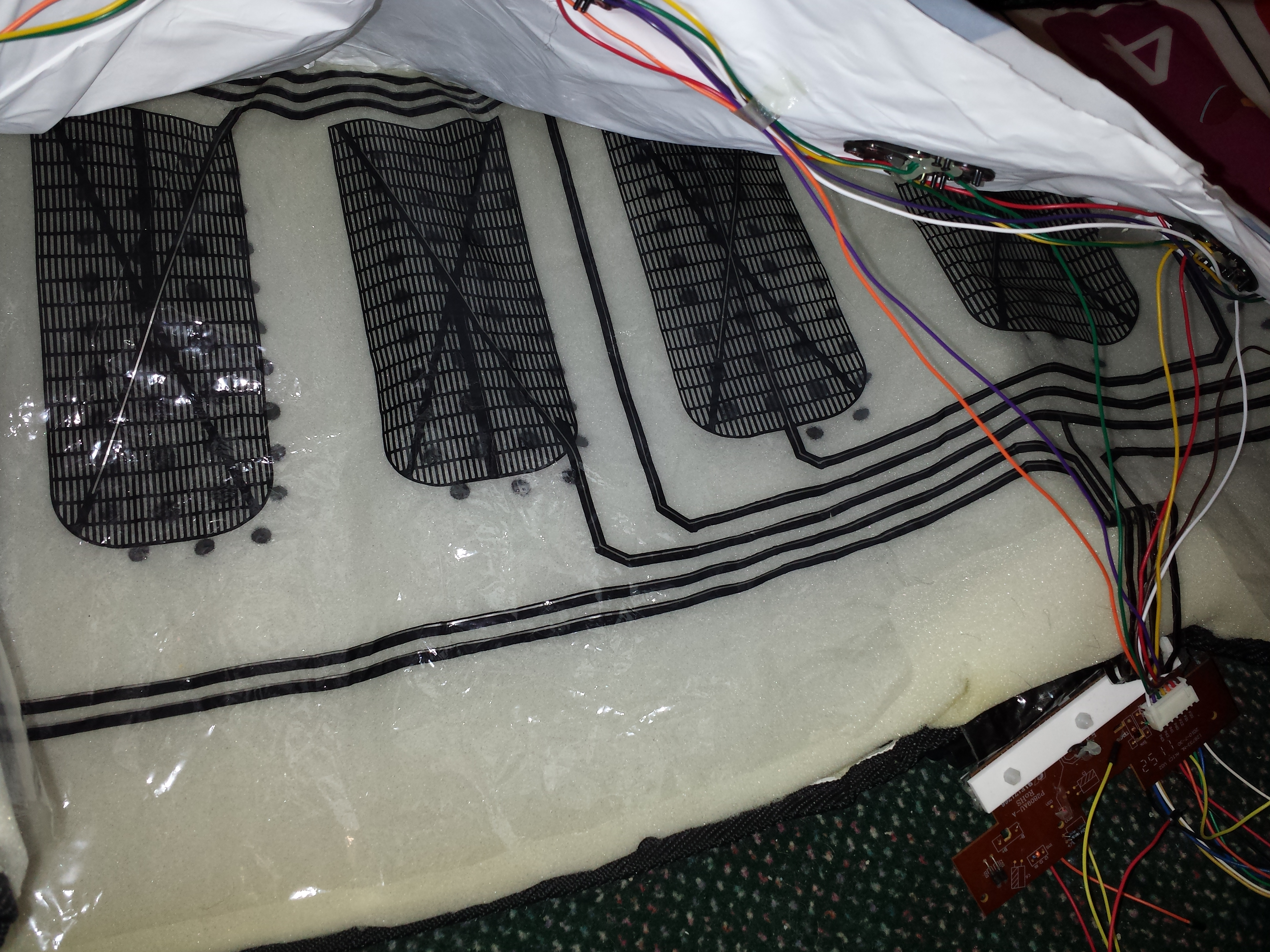
Unfortunately, the wiring of the buttons turned out to be even more confusing than those of the LEDs. Basically, inside the mat there are two layers of foil separated by a layer of foam. The foil has conductive areas at the position of each button as well as black lines that connect the buttons to the PCB in the toy. When pressure is applied to a button, the two layers are pressed together as the foam gets squashed, and a current can now flow between the two layers of foil. So you can model this button as a resistor that changes in resistance depending on the applied pressure. I hope the picture below makes everything a little bit clearer, where you can see one of the layers and the electrical connections in black, and the foam underneath obstructing the second layer below.
Similar to the buttons, the wiring was not straightforward, as you can see in the following schematics. For both layers, the connections accessible from the outside are drawn at the top.
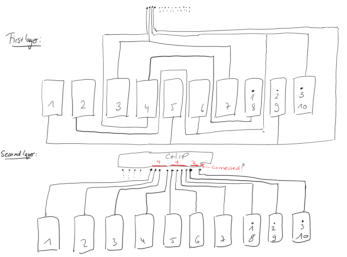
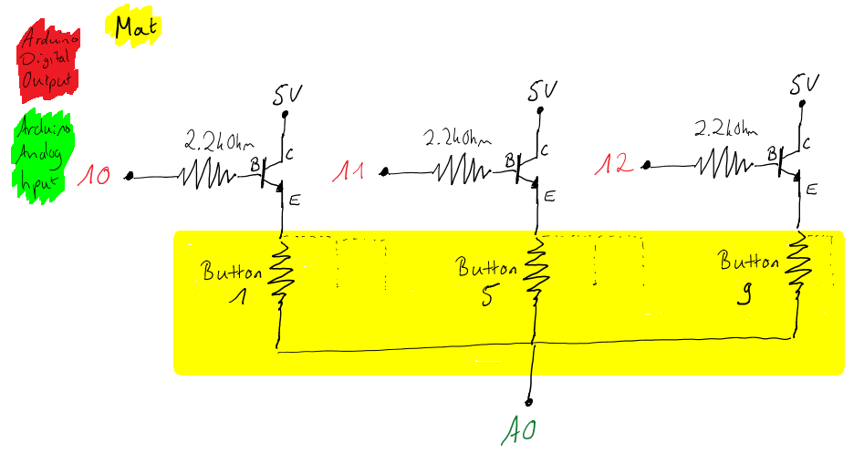
On the PCB, I discovered that the buttons 1-4, 5-8 and 9-10 were each short-circuited on the second layer, as shown in red in the schematic. This made matters much more complicated, because it again introduced dependencies between the buttons that make separate measurements of the buttons much harder. It leads to matrix setup, with four connections on the first and three connections on the second layer. Here is a diagram showing this matrix:
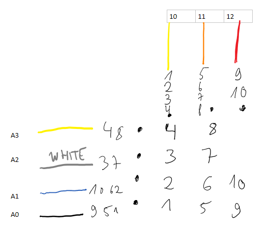
It assumes that current is applied on the digital pins 10 to 12 and the resulting voltage measured on the analog pins A0 to A3. For each coloured cable, the buttons that are connected to it are displayed. The matrix entries show the specific button addressed by the combination of two of these cables. So the idea is to apply HIGH to one of the three digital pins, while letting the other connections float, measuring the four analog voltages, and then selecting another digital pin to set to HIGH and repeat the procedure, and then do the same thing a final third time with the last remaining digital pin. The picture below shows a schematic of the Arduino setup for the analog pin A0 and demonstrates how setting exactly one pin between 10 and 12 to high allows for the measurement of the voltage for exactly one of the three buttons. It works analogously for the other analog pins A1 to A3.
Finally, I programmed my Arduino to periodically read these values, detect button presses using these measured voltages, and send the button states over the serial port, where they are received by the Unity game engine.
Game development in Unity
The video game itself was developed in Unity, which is a game development platform suited to build your own 3D as well as 2D games without going through the hassle of creating your own game engine and taking care of every little detail yourself. I can really recommend it to people interested in game development, because it represents a nice, accessible starting point for further endeavours.
Designing the 3D scene
One of Unity’s strength is definitely the modelling of 3D game environments. Although it can be difficult to find the right 3D models and textures for your game (and often you find many expensive offers on the internet and only few or no free ones), designing the terrain and moving, scaling and rotating objects is very intuitive and quickly done. Here is the scene of Snowfall as viewed inside the editor of Unity:
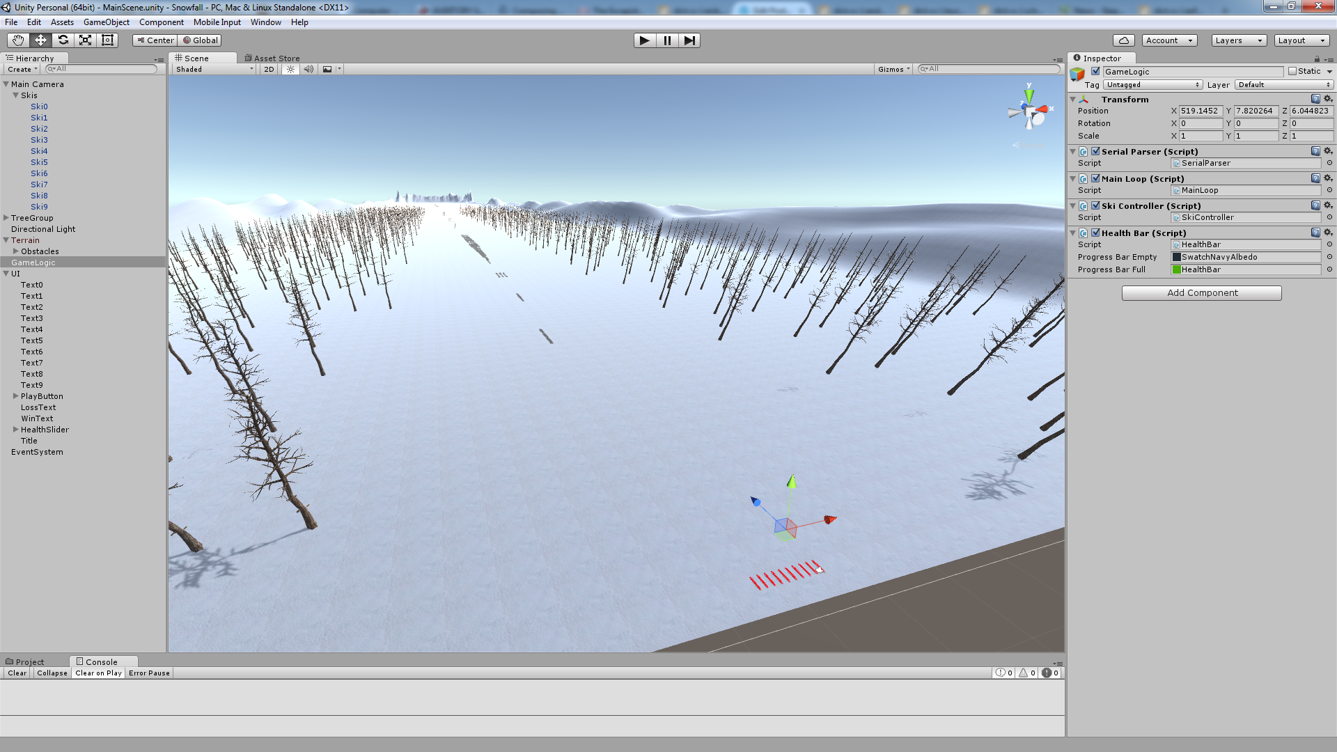
I quickly added some hills and a snow texture to the terrain, placed a lot of trees and obstacles (barely visible in the middle of the screen) and added 10 red skis with their positions relative to the main camera, so they move along with the player. Because the scene is rendered from the perspective of this main camera, for the player the skis do not seem to move at all. On the left side, you can see the scene hierarchy, containing all objects of the scene organised in a tree-like structure. As stated before, the skis are a child of the main camera object so that they do not change their position on the screen. The TreeGroup contains all trees, a directional light acts as the sunlight and the terrain features a set of obstacles in the form of many thin cuboids with a rocky texture. The UI consists of text labels from one to ten for every ski, a play button, a health slider, a title text for the start screen and a loss and win text shown when the player loses or wins. It is also simple to set it up so that a specific function in your own script is called every time the button is pressed or the slider is moved. Finally, the “GameLogic” object contains most of the C# scripts responsible for handling most of the game’s logic. I say most because some scripts are attached to specific game objects like the main camera.
Game logic with C# scripts
So now I designed a pretty 3D game world, but nothing is really happening in it and no interaction with the player is taking place - you could hardly call that a game, right? At first, I implemented moving the camera at a certain speed through the terrain, maintaining the same height and orientation, and gradually speeding up as we go through the level. I achieved this with a script attached to the Main Camera object containing the class “CameraController”. It defines a minimum and maximum speed in units per second as well as the acceleration additionalMinSpeedPerSec. A boolean variable determines if the camera should be moving at the moment - an external script can modify this variable to stop and start camera movement. Every frame, a call to the Update() function causes the current camera speed to be increased by Time.deltaTime * additionalMinSpeedPerSec, but limited to the maximum camera speed. Then, the camera is moved according to this currentCameraSpeed using the following code: Vector3 camPos = transform.localPosition; camPos.z += Time.deltaTime * currentCameraSpeed; transform.localPosition = camPos; Next, I implemented the desired reaction to detected collisions between skis and the rocky terrain. In the 3D scene, I already added box colliders to the obstacles and the skis and marked them as a trigger. Also, I added rigid bodies to the skis. Afterwards I attached a script to every ski whose class SkiCollisionDetector overrides the OnTriggerStay function which is called in regular intervals as long as a collision with the corresponding game object is detected. My implementation for every ski simply counts the total duration of the collisions in a variable collisionTime:
void OnTriggerStay(Collider coll)
{
        collisionTime += Time.deltaTime;
}
To maintain all ten skis in a comfortable way, I also implemented a SkiController that keeps a list of all skis, can add up all the collisionTime values of all skis to retrieve the total amount of damage, reset these variables back to zero in case a new game is started, and also set the visibility and the ability to trigger collision handling depending on the button states. The latter shall be explained in greater detail. The function setSkiStates(bool[] buttonStates) receives information about which buttons are currently pressed, goes through the skiList and makes only the skis belonging to those buttons visible and able to trigger the collision handling functions:
public void setSkiStates(bool[] buttonStates)
{
    for (int i = 0; i < skiList.Count; ++i) // Go through the ski list...
    {
        GameObject currentSki = ((GameObject)skiList[i]);
        currentSki.GetComponent().enabled = buttonStates[i]; // Ski is visible if its button is pressed
        currentSki.GetComponent().enabled = buttonStates[i]; // Ski can trigger calls of collision function (OnTriggerStay) if its button is pressed
    }
}
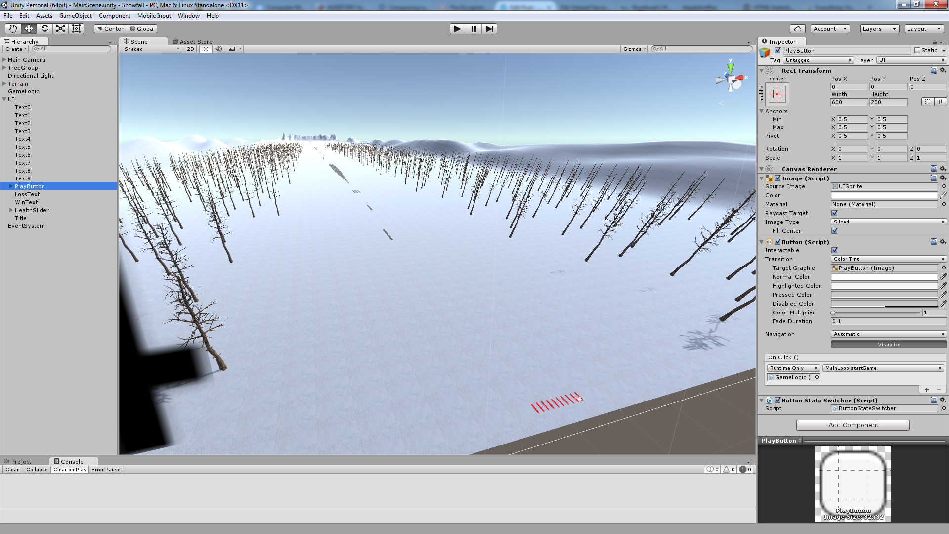
A HealthBar class uses GUI.DrawTexture with a black and a green texture to draw the health bar, using the black texture as a background and the green texture for the bar itself. Finally, a MainLoop class ties everything together and also reacts to pressing the play button and varying the health slider on the start screen. Setting up to have a specific function called when a specific UI element is interacted with is very easy, just select the UI element in the Unity editor and then, in the inspector on the right hand side, select the function you want to call. As an example, this screenshot shows my play button and how I set it up to call the function startGame of the class MainLoop contained in the game object GameLogic whenever it is pressed:
I will conclude this post with the code of the main loop during active gameplay. Hopefully, it is comprehensible with the extensive comments and can further develop your coding skills in Unity.
// Update is called once per frame
void Update()
{
    parser.readButtonStates(buttonStates); // Read the current button states
    skiController.setSkiStates(buttonStates); // Set ski visibility and collision triggering according to these button states

    if (gameActive) // If the game is active at the moment
    {
        float currentDamage = skiController.getSkiCollisionTime(); // Determine current collision time ("damage")
        float percentage = currentDamage / maxSeconds; // Determine ratio between damage and total health
        healthBar.setPercentage(1 - percentage); // Set health bar to reflect how many time is still available

        // Check for game ending conditions
        bool lossCondition = (percentage >= 1.0f); // Game lost if health percentage is above 1
        bool winCondition = (camController.transform.position.z >= 5300.0f); // Game won if camera has moved to the end of the level (camera moves along z axis only, starts at 0, at z=5300 the end of the level is reached)
        if (lossCondition || winCondition) // If a loss or a win occurred
        {
            gameActive = false; // Game is no longer active
            camController.setMoving(false); // Stop camera movement

            StartCoroutine(resetGame()); // Reset the game in 10 seconds

            if (winCondition) // Show winning text when won...
            {
                winText.enabled = true;
                print("WON");
            }
            else if (lossCondition) // ... otherwise show losing text
            {
                lossText.enabled = true;
                print("LOST");
            }
        }
    }
}